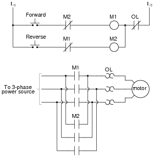
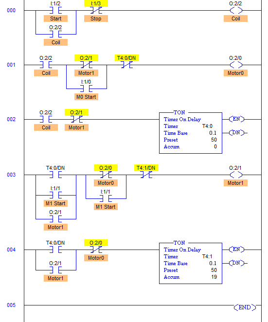
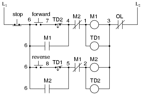
The plc implementation of this circuit should include the use of the overload contacts to monitor the occurrence of an overload condition. Figure 1 illustrates a hardwired forwardreverse motor circuit with electrical and push button interlockings.
Notice that the control section is the same as that used for reversing three phase motors.

You can find out more Diagram below
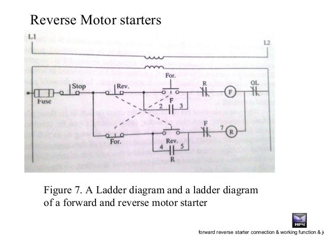
Forward reverse motor control ladder diagram. Now if either forward or reverse circuits are latched they may be unlatched by momentarily pressing the stop pushbutton which will open either forward or reverse circuit de energizing the energized contactor and returning the. This is plc program for forward and reverse control for 3 phase asynchronous motor. Plc application for forwardreverse motor circuit on photo.
Posted on december 9 2015 by admin leave a comment. 3 phase motor control using plc. Configure forward and reverse wiring of the motor with contactors such that forward contactor is connected directly in the normal direct phasing of the.
The direction of rotation of any three phase motor can be reversed by changing any two motor t leads l1 figure 291. Plc ladder diagram motor forward and reverse with interlocking. I hope you will share this post on social media.
Well call this new switch stop. Read about motor control circuits ladder logic in our free. Run this motor in the forward and reverse direction using ladder diagram programming language.
There are lots of motors and conveyors used in industries for different purposes. Now if you have any question and have any suggestion then you can use the below comments box. I hope the above forward reverse motor control diagram 3 phase motor forward reverse starter wiring diagram help you to understand this connection.
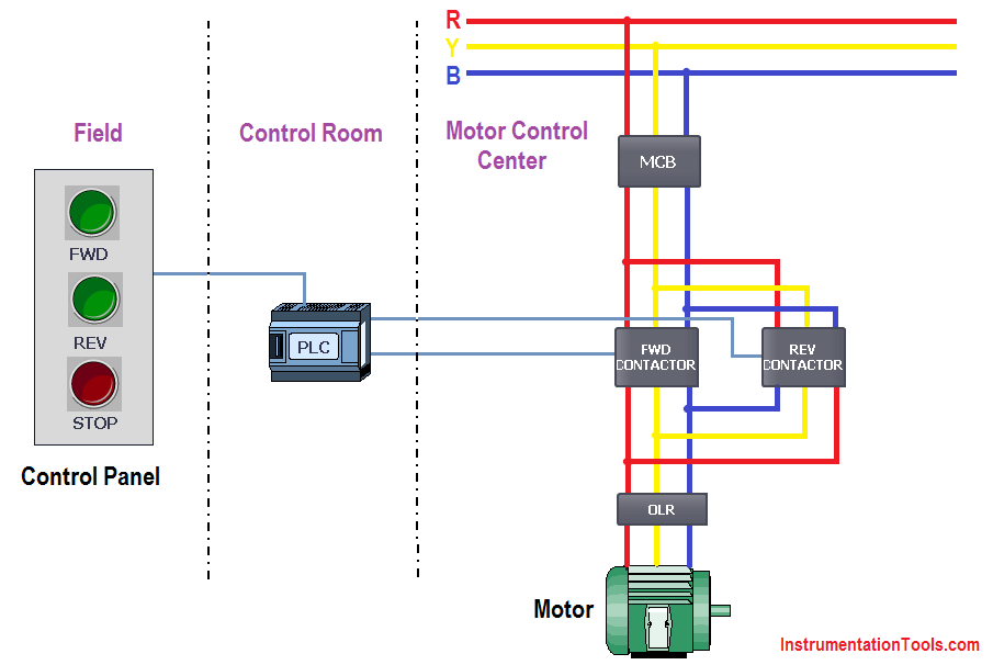
A schematic diagram of a forward reverse control for a single phase split phase motor is shown in figure 2913. Fwd rev contactor for 3 phase motor. This video will walk you through the standard forward reverse contactor ladder diagram cw electrical and mechanical interlocking.
Only push button switches are used to control the direction of this three phase ac motor. In some cases motors or conveyors need forward and reverse operation for some control purpose. Figure 1 illustrates a hardwired forwardreverse motor circuit with electrical and push buttoninterlockingsfigure 2 shows the simplified wiring diagram for this motor.







0 comments:
Post a Comment