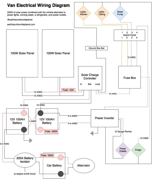
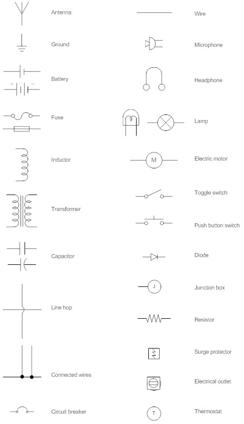
Adding new wiring from ceiling boxes. For help understanding them be sure to open the explanation page.
Red and black wires denote live wires white wires serve as the ground and blue yellow or other colors are used for switches or other specific purposes.
You can find out more Diagram below
Electricity wiring diagram. How electricity reaches our homes from the power station. Wiring diagrams for 3 way switches diagrams for 3 way switch circuits including. Electrical wiring in the us follows the same basic color codes.
Wiring diagrams device locations and circuit planning a typical set of house plans shows the electrical symbols that have been located on the floor plan but do not provide any wiring details. A wiring diagram is a simple visual representation of the physical connections and physical layout of an electrical system or circuit. Illustrated wiring diagrams for home electrical projects.
Residential electric wiring diagrams are an important tool for installing and testing home electrical circuits and they will also help you understand how electrical devices are wired and how various electrical devices and controls operate. This outlet is commonly used for a heavy load such as a large air conditioner. It shows how the electrical wires are interconnected and can also show where fixtures and components may be connected to the system.
The outlet should be wired to a dedicated 20 amp240 volt circuit breaker in the service panel using 122 awg cable. In this video we learn electrical engineering basics by learning single phase meter wiring diagram. It gives you over 200 diagrams.
Single phase electricity explained. With this wiring both the black and white wires are used to carry 120 volts each and the white wire is wrapped with electrical tape to label it hot. Wiring connections in switch outlet and light boxes the following house electrical wiring diagrams will show almost all the kinds of electrical wiring connections that serve the functions you need at a variety of outlet light and switch boxes.
Wiring a 20 amp 240 volt appliance receptacle. Ford wiring diagrams electrical schematics circuit diagrams free download. Residential electrical wiring diagrams summary.
Ford wiring diagrams electrical schematics circuit diagrams free download. With the light at the beginning middle and end a 3 way dimmer multiple lights controlling a receptacle and troubleshooting tips. Basic electrical home wiring diagrams tutorials ups inverter wiring diagrams connection solar panel wiring installation diagrams batteries wiring connections and diagrams single phase three phase wiring diagrams 1 phase 3 phase wiringthree phase motor power control wiring diagrams.
As is shown in the diagram to the right.


0 comments:
Post a Comment