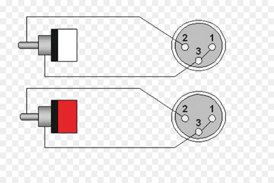
The above diagram shows you the pin numbering for both male and female xlr connectors from the front and the rear view. As i outlined above the wiring is different which way you go.
Wiring diagram schematics pertaining to hdmi to rca cable wiring diagram image size 589 x 542 px and to view image details please click the image.

You can find out more Diagram below
Xlr to rca wiring diagram. 3 pin xlr connectors are standard amongst line level and mic level audio applications. Pin 1 of the xlr connects to the sleeve of both rca plugs. The positive and shield of the xlr are joined together either at the xlr end or the rca end.
Rca to xlr are hard to find. This produces an unbalanced audio cable. An xlr connector on one side may be male or female depending on the component an rca plug on the other side and three wires to connect them.
If the signal source is equipped with a cross coupled output stage. The parts needed are relatively self explanatory. Hdmi to rca cable wiring diagram.
Audio cableconnector wiring diagrams female balanced xlr to male unbalanced rca fig. The easiest way is to solder a link between pins 1 and 3 shield and negative of the xlr rather than trying to solder the shield and negative wire to the sleeve contact of the rca. Most of these cables are xlr to rca.
Xlr to 1x rca. Thankfully we have a standard for wiring xlr connectors used in audio mic level line level and lighting control dmx applications. The problem is that with pre made cables you can never be sure they are described correctly.
B h have this 2 cable which will do the trick as he can extend it with an rca to rca cable. He needs rca to xlr and not xlr to rca. This produces an unbalanced audio cable.
If the signal source is equipped with a pseudo balanced output stage. It shows the components of the circuit as simplified shapes and the capacity and signal connections in the midst of the devices. Xlr to 2x rca a 3 pin xlr with a stereo signal can be split into left and right by wiring pin 2 of the xlr to the tip of one rca plug and pin 3 of the xlr to another rca tip.
In this case an xlr to rca cable can be used. Pin 1 of the xlr connects to the sleeve of both rca plugs. One can also use only two wires and short the xlr internally between pins one and three.
Xlr to rca wiring diagram wiring diagram is a simplified customary pictorial representation of an electrical circuit. Vga connector wiring diagram vga connector wiring diagram vga for hdmi to rca cable wiring diagram image size 434 x 473 px and to view image details please click the image. Rca to xlr wiring diagram thanks for visiting our site this is images about rca to xlr wiring diagram posted by maria nieto in rca category on may 09 2019.


0 comments:
Post a Comment